Glenair has been a qualified supplier of MIL-DTL-38999 solutions for over a decade. All our Mil-Aero connector technologies are 100% first world manufactured, with zero material, component part or labour sourced in China, Mexico or other off-shore environments.
Glenair brings a new perspective to the supply of high-performance Mil-Spec and commercial electrical contacts: High Availability! Whether you need a standard duty socket contact for a MIL-DTL-28840 connector or a short-run of shielded Quadrax, we have you covered with products that are always in stock
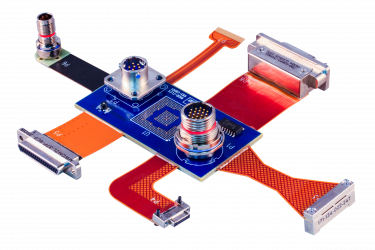
Flex Circuit Assemblies are an alternative to standard wire in electrical interconnect systems. Designed to reduce size and weight, flex circuits utilise thin layers of polymer film as a dielectric sandwiched between conductive circuit patterns etched into layers of copper foil cladding.
Series GMMD is an innovative modular Micro-D connector for RF coax and high-speed differential datalink applications. The unique micro-miniature design of the GMMD also accommodates standard analogue signal and power contacts, making it the most versatile Micro-D rectangular in the industry.
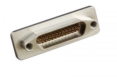
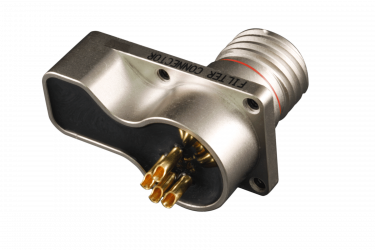
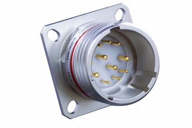
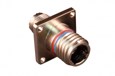
Hermetic connectors are a special class of Mil /Aero interconnect that incorporates glass-to-metal or other highly-engineered sealing technology. Hermetic connectors are specified for applications as divergent as submarines and orbiting satellites.
High-speed connectors and contacts are optimized for compatible performance with popular data transmission protocols.
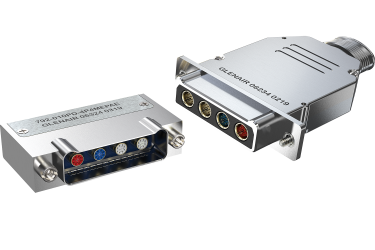
Multi-Port Rectangular Connector for High-Speed Wire-to-Board Applications
10G Ethernet • USB 3.0 • HDMI • SATA • DisplayPort
If you're looking for a rugged, versatile, multi-port, multi-gigabit connector, the Series 792 with shielded contact technology is an ideal solution.
Glenair's Complete Micro-D Product Line includes Solder Cup, Pre-Wired or PCB versions. Glenair Micro-D connectors always use TwistPin Contacts for high performance.
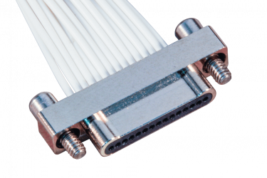
The smallest and lightest mil-qualified connector series. The Nano range is ideally suited for rugged defence and aerospace wire-to-board applications.
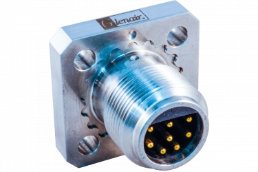
Radiation resistant, temperature resistant, chemical and fluid resistant, corrosion resistant, stainless steel connectors for Zone 1E containment area nuclear industry interconnect applications.
The Faster 4/8 Pole Interconnect System for Ethernet Data Applications
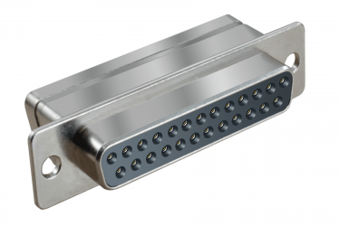
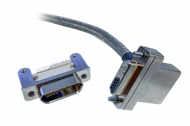
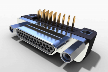
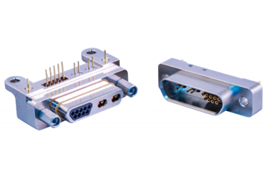
Glenair manufactures all of the popular industry-standard rectangular connectors used in military, aerospace and other high reliability applications, including special high-performance versions of the M24308 D-Sub and our revolutionary Series 79 Micro-Crimp connector.
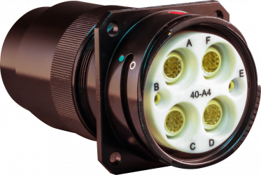
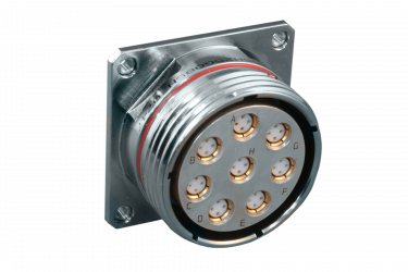
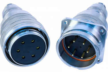
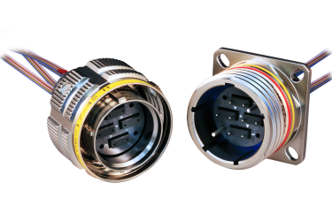
The Series 23 SuperNine® advanced performance MIL-DTL-38999 connector series rolls up many of the technology advances Glenair has pioneered in our environmental, hermetic, and filter connectors into a comprehensive high-performance MILDTL-38999 Series III solution.
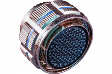
Ruggedized, High-Density MT Ferrule Fiber Optics in Aerospace-Grade MIL-DTL-38999 Connectors
MT fiber optic ferrules are super-high-density commercial interconnect inserts that accommodate up to 24 fibers in a compact and lightweight package.
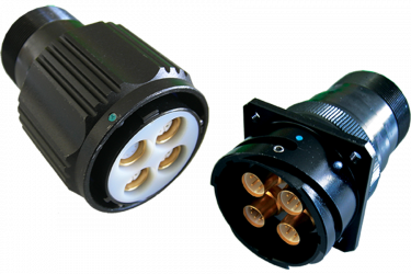
Save Size and Weight, and Improve Performance with Glenair Micro-Miniature Interconnects, Including Industry-Leading Mighty Mouse and SuperFly Solutions.
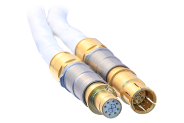
Glenair excels in the design and manufacture of high-pressure, underwater connectors and interconnect cable assemblies for electrical and fiber optic applications.
VersaLink™ delivers outstanding impedance matching and cross-talk isolation at both the cable-to-connector interface, as well as between connector and board. VersaLink is a highly-engineered differential Twinax contact module that may be packaged in a wide range of both circular and rectangular connector formats such as the MIL-DTL-83513 Micro-D.
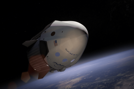
Glenair's history of interconnect innovation for manned space applications began with our design and fabrication role in the realization of the golden umbilical life-support cable used by Commander Ed White in the first American Gemini Program space walk in 1965.
Christopher J. Toomey - Glenair President.
Read full case study
eVTOL Air Taxi Interconnect Solutions - Signature Interconnect Technology for Urban Air Mobility Aircraft Including Connectors for Distributed Power Propulsion Systems, Avionics, Actuators, and Sensors.
QwikConnect - July 2021
Read full case study